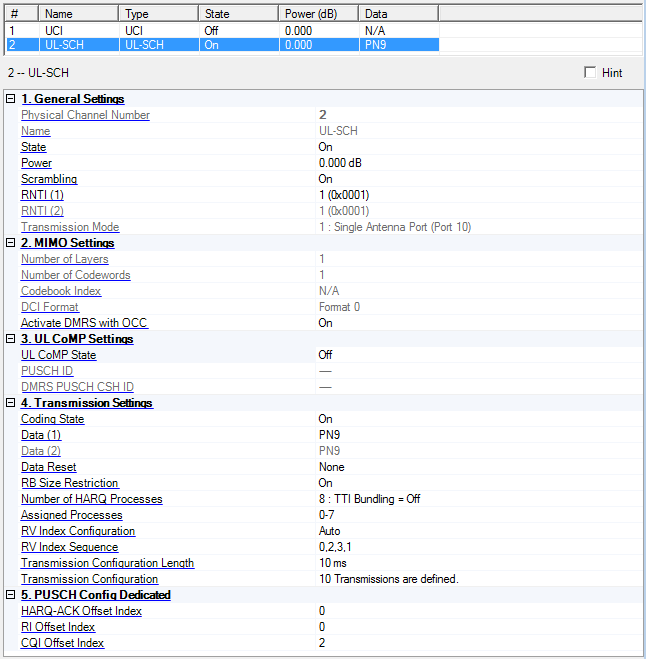
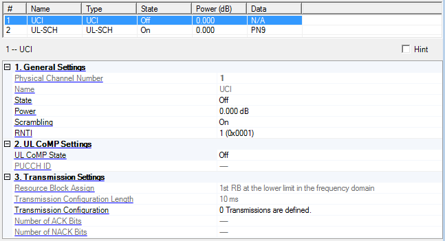
Displays the identifying number of the selected channel.
Displays the name of the selected channel.
UCI = Uplink Control Information
UL-SCH = Uplink Shared Channel
Choice: Off | On
Default: Off
Double-click or use the drop-down menu to turn the selected channel off or on.
UCI Parameters: If the total number of antennas is set to 4 under the Uplink Cell Parameters, the state is set to off and is read only.
Range: -60.000 to 20.000 dB
Default: 0.000 dB
Enter a power level in dB for the selected channel. See Output Power Calculation (Uplink) for a description of how the software applies your power setting.
Choice: Off | On
Default: On
Double-click or use the drop-down menu to turn scrambling for the physical channel on or off.
Range: 0 to 65535 (0x0000 to 0xFFFF)
Default: 1 (0x0001)
Enter the Radio Network Temporary Identifier (RNTI) for the corresponding PUCCH transmission.
The input method can be in decimal format or hexadecimal format.
Example: The decimal input "15" is displayed as "15 (0x000F)" and the hexadecimal input "0xf" is displayed as "15 (0x000F)".
See 3GPP TS 36.211 and 36.321, for more information.
Range: 0 to 65535 (0x0000 to 0xFFFF)
Default: 1 (0x0001)
Enter the Radio Network Temporary Identifier (RNTI) for transport block 1 (codeword 0).
The input method can be in decimal format or hexadecimal format.
Example: The decimal input "15" is displayed as "15 (0x000F)" and the hexadecimal input "0xf" is displayed as "15 (0x000F)".
See 3GPP TS 36.211 and 36.321, for more information.
Range: 0 to 65535 (0x0000 to 0xFFFF)
Default: 1 (0x0001)
Enter the Radio Network Temporary Identifier (RNTI) for transport block 1 (codeword 1).
The input method can be in decimal format or hexadecimal format.
If the "number of codewords" parameter is 2, this parameter is displayed. Otherwise it is hidden.
Example: The decimal input "15" is displayed as "15 (0x000F)" and the hexadecimal input "0xf" is displayed as "15 (0x000F)".
See 3GPP TS 36.211 and 36.321, for more information.
Displays the transmission mode for the corresponding PUSCH transmission.
The Transmission Mode is dependent on the Total Number of Antennas used.
Transmission Mode 1 is used for single antenna transmission and Transmission Mode 2 is used for multi-antenna transmission.
1 : Single Antenna Port (Port 10) Default when 1 Antenna is selected under Uplink Cell Parameters
2 : Single Antenna Port (Port 10) / Closed Loop Spatial Multiplexing Default when 1 or 4 Antenna(s) is(are) selected under Uplink Cell Parameters
See 3GPP TS 36.211 and 36.213, for more information.
Choice: (Dependent on the Total Number of Antennas.)
1 (1 Antenna case) Default =1 when 1 Antenna is selected under Uplink Cell Parameters
1 | 2 (2 Antennas case) Default =2 when 2 Antennas are selected under Uplink Cell Parameters
1 | 2 | 3 | 4 (4 Antennas case) Default =4 when 4 Antennas are selected under Uplink Cell Parameters
Double-click or use the drop-down menu to select the number of layers for the corresponding PUSCH transmission. The number of layers is less than or equal to the number of antennas.
Choice: Dependent on the Total Number of Antennas and Number of Layers.)
1 (1 Antenna case) Default when 1 Antenna is selected under Uplink Cell Parameters
1 (2 Antennas, 1 Layer case)
2 (2 Antennas, 2 Layers case) Default when 2 Antennas are selected under Uplink Cell Parameters
1 (4 Antennas, 1 Layer case)
1 | 2 (4 Antennas, 2 Layers case) Default =2 when 4 Antennas are selected under Uplink Cell Parameters
2 (4 Antennas, 3 Layers case)
2 (4 Antennas, 4 Layers case)
Default: 1
Double-click or use the drop-down menu to select the number of codewords for the corresponding PUSCH transmission.
See 3GPP TS 36.211, 36.212 and 36.213, for more information.
Range: (Dependent on the Total Number of Antennas, Number of Layers, and DCI Format.)
N/A (DCI Format 0 case) Default when 1 Antenna is selected under Uplink Cell Parameters or when DCI Format is set to Format 0.
0 to 5 (2 Antennas, 1 Layer case)
0 (2 Antennas, 2 Layers case) Default when 2 Antennas are selected under Uplink Cell Parameters
0 to 23 (4 Antennas, 1 Layer case)
0 to 15 (4 Antennas, 2 Layers case) Default when 4 Antennas are selected under Uplink Cell Parameters
0 to 11 (4 Antennas, 3 Layers case)
0 (4 Antennas, 4 Layers case)
Enter the codebook index for the corresponding PUSCH transmission.
In case of DCI Format 0, N/A is displayed.
See 3GPP TS 36.211, 36.212 and 36.213, for more information.
Choice: (Dependent on the Total Number of Antennas, Number of Layers and Number of Codewords.)
Format 0 (1 Antenna case) Default when 1 Antenna is selected under Uplink Cell Parameters
Format 0 | Format 4 (2 Antennas, 1 Layer, 1 Codeword case) Default =4 when 2 Antennas are selected under Uplink Cell Parameters
Format 0 | Format 4 (4 Antennas, 1 Layer, 1 Codeword case) Default =4 when 4 Antennas are selected under Uplink Cell Parameters
Default: Format 0
Double-click or use the drop-down menu to select the DCI Format for the corresponding PUSCH transmission.
See 3GPP TS 36.211, 36.212 and 36.213, for more information.
Choice: On | Off
Default: On
Double-click or use the drop-down menu to set the Activate-DMRS-with OCC parameter on or off for the corresponding PUSCH transmission.
See 3GPP TS 36.211 and 36.331, for more information.
Choice: On | Off
Default: Off
Double-click or use the drop-down menu to turn the state On or Off.
|
|
On |
|
PUSCH ID and DMRS PUSCH CSH ID are available to set a value |
|
|
Off |
|
PUSCH ID and DMRS PUSCH CSH ID are read only |
See 3GPP TS 36.211 and 36.311 for more information.
Choice: On | Off
Default: Off
Double-click or use the drop-down menu to turn the state On or Off.
|
|
On |
|
PUCCH ID is available to set a value |
|
|
Off |
|
PUCCH ID is read only |
See 3GPP TS 36.211 and 36.311 for more information.
Range: 0 to 509
Default: 0
Coupling: Read only value unless UL CoMP State is set to On
Enter a value for the PUSCH Identity (ID) that is used for the virtual cell ID.
See 3GPP TS 36.211 and 36.311 for more information.
Range: 0 to 509
Default: 0
Coupling: Read only value unless UL CoMP State is set to On
Enter a value for the PUCCH Identity (ID) that is used for the virtual cell ID.
See 3GPP TS 36.211 and 36.311 for more information.
Range: 0 to 509
Default: 0
Coupling: Read only value unless UL CoMP State is set to On
Enter a value that is used in the initialization of the cyclic shift hopping for the generation of the DMRS PUSCH pseudo random sequence. This is used for the virtual cell ID.
See 3GPP TS 36.211 and 36.311 for more information.
Choice: Off | On
Default: On
This parameter applies only to UL-SCH channels.
Double-click or use the drop-down menu to turn coding for the selected channel off or on.
If the Number of HARQ Processes is set to 3 or 4, the Coding State is set to On as read-only.
Use the Data Source Selection dialog box to select PN9, PN15, or User Defined Bits or user defined bits to use for the data in the transport block 1 (codeword 0).
See 3GPP TS 36.211, 36.212 and 36.213, for more information.
This parameter applies only to UL-SCH channels.
Use the Data Source Selection dialog box to select PN9, PN15, or User Defined Bits or user defined bits to use for the data in the transport block 2 (codeword 1).
See 3GPP TS 36.211, 36.212 and 36.213, for more information.
Choice: None | Every Subframe
Default: None
Sets the data reset method for UL-SCH.
None: the transport data is continuously repeated seed data which is specified by Data parameter. The transport data is not reset till end of waveform.
Every Subframe: the transport data is reset at the start of each subframe.
If Number of HARQ Processes is 3 or 4, Data Reset is set to None as read-only.
If UE Type is BL/CE, Data Reset is set to Every Subframe as read-only.
For eMTC Uplink CC, this parameter is set to Every Subframe first as an exception.
This parameter appears in the software's GUI only when Minor Enhancement Update (MEU) Option U01 or greater is valid. Refer to Licenses for more information.
Choice: On | Off
Default: On
Double-click or use the drop-down menu to turn the PUSCH Resource Block Size Restriction on or off.
If it is On, PUSCH Resource Block Size is restricted equal to (2^(a*2)) * (2^(b*3)) * (2^(c*5)) or less than RB UL max. (a, b, c is non-negative integer).
This resource restriction is according to the 3GPP standard specification.
Otherwise it is just equal or less than RB UL max. (RB UL max is system RB size)
See 3GPP TS 36.211 for more information.
Choice: 3 | 4 | 8
Default: 8
Double-click or use the drop-down menu to select the number of HARQ Processes. This parameter applies only to UL-SCH channels.
This value decides the number of available hybrid automatic repeat request (HARQ) processes and defines the interval (number of subframes) between retransmissions. Use the Assigned Processes parameter to enable HARQ processes.
3 : TTI Bundling = On and e-HARQ-Pattern = On (MEU Option U05 or greater only)
4 : TTI Bundling = On and e-HARQ-Pattern = Off (MEU Option U05 or greater only)
8 : TTI Bundling = Off
If the Number of HARQ Processes is set to 3 or 4, TTI Bundling is set to On (Bundling operation).
If the Number of HARQ Processes is set to 8, TTI Bundling is set to Off (Normal operation).
Click the button in the Transmission Configuration parameter to view the enabled HARQ processes in the UL-SCH Tx sequence window.
If UE Type is BL/CE, Number of HARQ Process is set to 8 as read-only.
See 3GPP TS 36.213, 36.321 and 36.311 for more information.
This parameter includes choices 3 and 4 only when Minor Enhancement Update (MEU) Option U05 or greater is valid. It is also read-only without MEU. Refer to Licenses for more information.
Range: 0 to (number defined in Number of HARQ Processes)
Default: 0 to 7
This parameter applies only to UL-SCH channels.
Enter the numbers of individual HARQ processes, separated by commas (for example, 1,2,3) or a range of HARQ processes ( for example, 1-3) to enable specific HARQ processes. The number of available HARQ processes is defined in the Number of HARQ Processes cell.
Your setting is displayed in the UL-SCH Tx sequence window (see Transmission Configuration).
Choice: Auto | Manual
Default: Auto
Double-click or use the drop-down menu to set the RV Index Configuration.
If the RV Index Configuration is set to Auto, the RV index is automatically set in order from the first element of RV index sequence.
If the RV Index Configuration is set to Manual, you can set RV index manually in the UL-SCH Tx sequence window.
If the Number of HARQ Processes is 3 or 4, the RV Index Configuration is set to Auto as read-only.
This parameter appears only when UE Type is set to Non-BL/CE.
Range of sequence length: 1 to 16
Range of each value: 0 to 3
Default: 0,2,3,1
Enter the numbers of individual RV Index Sequence, separated by commas (for example, 1,2,3).
In the case that Number of HARQ Processes is 8 (TTI Bundling is off) and RV Index Configuration is 'Manual', RV Index Sequence is read-only.
If the Number of HARQ Processes is 3 or 4, the RV Index Sequence is set to 0,2,3,1 as read-only.
This parameter applies only to UCI channels. Select a resource block assignment for the UCI from the drop-down list. Your selection is applied to the UCI in the first slot of each subframe. The UCI in the second slot of each subframe is adjusted accordingly. Your setting is displayed in the resource mapping graph at the bottom of the Channel Setup window.
Range:
Non-BL/CE: 10 ms to Waveform Generation Length, Max 160 ms
BL/CE: 1 ms (Fixed)
Step: 10 ms
Default: 10 ms
This value is set same value of Transmission Configuration Length in UL-SCH as read-only automatically.
If the Waveform Generation Length parameter is set less than the Transmission Configuration Length, the value of Transmission Configuration Length is changed to be ≤Waveform Generation Length. In summary, the relation between Transmission Configuration Length and Waveform Generation Length is that the Transmission Configuration Length ≤Waveform Generation Length. Refer to the Waveform Generation Length parameter.
|
Channel |
Transmission Configuration Length |
Default Value |
|---|---|---|
|
UL-SCH |
The value is available to set 1 -16 Frames With following rule: Transmission Configuration Length ≤Waveform Generation Length |
10 ms |
|
UCI |
The value is automatically set to same value corresponding UL-SCH. |
Same as UL-SCH |
Example: Where the Transmission Configuration Length is set to 20 ms (2 frames), Frames #0 and #1 configurations (Sequences #1 through #20) will be repeated while generating  SCH.
SCH.
Select an uplink channel, then click the  button in this cell to open the UL-SCH
Tx sequence window, or the UCI
Tx sequence window.
button in this cell to open the UL-SCH
Tx sequence window, or the UCI
Tx sequence window.
Displays the total number of ACK bits on the definition of UCI Transmission Configuration as generated by the PUCCH Wizard.
Displays the total number of NACK bits on the definition of UCI Transmission Configuration as generated by PUCCH Wizard.
Range: 0 to 15
Default: 0
Enter a value for the HARQ-ACK Offset Index. The table below shows the relationship between the HARQ-ACK offset value and the HARQ-ACK Offset Index:
|
|
|
|---|---|
|
0 |
2.000 |
|
1 |
2.500 |
|
2 |
3.125 |
|
3 |
4.000 |
|
4 |
5.000 |
|
5 |
6.250 |
|
6 |
8.000 |
|
7 |
10.000 |
|
8 |
12.625 |
|
9 |
15.875 |
|
10 |
20.000 |
|
11 |
31.000 |
|
12 |
50.000 |
|
13 |
80.000 |
|
14 |
126.000 |
|
15 |
reserved |
Range: 0 to 12
Default: 0
Enter a value for the RI Offset Index. The table below shows the relationship between the RI offset value and the RI Offset Index:
|
|
|
|---|---|
|
0 |
1.250 |
|
1 |
1.625 |
|
2 |
2.000 |
|
3 |
2.500 |
|
4 |
3.125 |
|
5 |
4.000 |
|
6 |
5.000 |
|
7 |
6.250 |
|
8 |
8.000 |
|
9 |
10.000 |
|
10 |
12.625 |
|
11 |
15.875 |
|
12 |
20.000 |
|
13 |
reserved |
|
14 |
reserved |
|
15 |
reserved |
Range: 2 to 15
Default: 2
Enter a value for the CQI Offset Index. The table below shows the relationship between the CQI offset value and the CQI Offset Index:
|
|
|
|---|---|
|
0 |
reserved |
|
1 |
reserved |
|
2 |
1.125 |
|
3 |
1.250 |
|
4 |
1.375 |
|
5 |
1.625 |
|
6 |
1.750 |
|
7 |
2.000 |
|
8 |
2.250 |
|
9 |
2.500 |
|
10 |
2.875 |
|
11 |
3.125 |
|
12 |
3.500 |
|
13 |
4.000 |
|
14 |
5.000 |
|
15 |
6.250 |